#devblog
Sharing, ranting, showing-off :)
Engines, and it's limitations
Nov 15, 2020
In this article, we go through all the engine-related systems, how they work and how they are inter-connected in detail.
The Let L-410 is powered by two Walter/General Electric Turbo-Propeller engines. The engines have several protections and redundancy mechanisms and are equipped with a water injection system which has the effect of reducing density altitude at ambient temperatures above 23°C.
System Description
The Walter/General Electric M601E Engine is a free turbine, reverse flow engine incorporating a hybrid compressor (using two axial compressor stages and one centrifugal stage) and a single-stage power turbine driving an Avia V510 five-bladed, constant speed reversible propeller via a reduction gearbox.
A Starter/Generator is permanently geared to the accessory gearbox at the rear of the engine, providing power for start, afterwards switching to generator mode to develop 28V DC power for aircraft systems.
The propeller is equipped with an Auto-Feather feature, which together with the Auto Bank Control tabs (below 205kmh/111KIAS) minimise the effect of asymmetric thrust in the event of an engine failure.
IELU limits the engine’s parameters, except after a single-engine failure, in which case the reserve power of the remaining engine can be utilised. At 100% Torque and 2080 NP, 750 shaft horsepower is produced. Using reserve power for a maximum of 106.5% Torque for a maximum of six minutes, 798 shp can be achieved (Maximum Contingency Power). In the case of an engine failure and selection of Maximum Contingency Power, the operation of the ABC tabs may be necessary below 205kmh/111KIAS to maintain directional control.
System Detail
Air is inducted into the rear of the engine. The engine air intake, which encircles the engine body, is protected by a wire mesh which guards against ingestion of large objects. Items such as plastic bags can seriously disrupt the airflow as it can block a large section of the intake.
Air is compressed via two axial flow compressor stages and a centrifugal compressor as a final stage, before entering the combustion chamber. As the compression characteristics of an axial and centrifugal compressor differ across the engine RPM (N1) range, a Blow-Off Valve (also referred to as Bleed Valve or Spill Valve) discharges excess air delivered by the axial flow compressor, up to 90% - 93% N1. The correct operation of this valve is checked before take-off, by opening the power to 20% Torque and noting a decrease in ITT. This signifies that the Blow-Off Valve is closed and the mass airflow through the engine has increased.
Compressed air used by the aircraft (pneumatic services, intake lip and cabin heating) is taken from the discharge section of the centrifugal compressor.
A Tachy Generator is geared to the compressor via the Accessory Gearbox (more detail on this later), which generates a voltage according to the RPM of the Gas Generator, referred to as N1, or sometimes NG on other engines. This is displayed as a percentage on the N1 Gauge. As the system generates its power, it does not need electricity from the aircraft.
Air enters the Combustion Chamber at various zones, firstly near the centre of the engine to establish an airflow pattern and burning zone, as well as “downstream” in the combustion chamber, to maintain a buffer zone of cooler air between the burning air/fuel mixture and the combustion chamber lining. By introducing fresh air in the combustion chamber, the air/fuel mixture will have more complete combustion; this process is known as the dilution of the air/fuel mixture. P3 air (discharge from the centrifugal compressor) flows through the Nozzle and Interstage Guide Vanes for cooling.
The point of highest pressure in the engine is the delivery pressure of the centrifugal compressor. From there, taking into account the rapid increase in gas temperature and velocity due to combustion, by aerodynamic design the engine follows an overall convergent nozzle principle where the velocity of the gas-flow will increase, while pressure and temperature will decrease. Thus the gas-flow pressure in the combustion chamber is always lower than that of the surrounding air in the discharge chamber of the centrifugal compressor, and through various holes air enters the combustion chamber, as said to maintain the flame away from the combustion chamber lining as well as to dilute the air/fuel mixture.
As the expanding gasses accelerate out of the combustion chamber, the energy of the fuel has been converted into heat (at full power the gas temperature can exceed 900°C) as well as kinetic energy as the gasses accelerate. In essence, the combustion chamber delivers high energy gas to drive the turbines.
Being somewhat turbulent after the combustion process and mixing, the gasses are directed through Nozzle Guide Vanes. Because of the convergent duct aerodynamic design, the Nozzle Guide Vanes further accelerate the air. There are a slight temperature and pressure drop across these vanes.
The directed gases pass through the Compressor Turbine, imparting significant amounts of energy (about two-thirds) to the turbine to drive the compressor - causing a significant drop in pressure, temperature and velocity of the gas flow.
Inter-stage Guide Vanes guide the air onto the Power Turbine, which spins in the same direction as the Compressor Turbine.
Between the Guide Vanes and the Power Turbine, nine Inter-stage Turbine Temperature (ITT) probes measure the temperature of the gas flow. This is achieved by thermo-couples converting temperature into electrical current, which is displayed on an ITT Gauge. An interesting design feature is that the current is sufficient enough to drive the ITT Gauges, thus the system is self-powering and will function with no other electrical power on the aircraft.
Installing these probes on the upstream side of the Compressor Turbine would expose the probes to much higher gas temperatures, where it will fail in very short order, not being air-cooled such as the Nozzle Guide Vanes or made of expensive alloys such as the Compressor Turbine. As there is a significant temperature drop across the Compressor Turbine, a reading of 735°C equates to a gas flow temperature onto the Compressor Turbine being very close to the fatigue point of the metal, thus care must be exercised during take-off not to exceed the maximum ITT. The IELU’s of the Let 410 will limit the ITT.
The gases pass through the Inter-stage Guide Vanes and onto the Power Turbine, which drives the Reduction Gearbox and Propeller. The Power Turbine will turn at very high RPM but low torque, it is the function of the Reduction Gearbox to convert this into low RPM but high torque. The RPM of the Power Turbine is controlled primarily by the Propeller Governor, as it is directly geared to the propeller. A Tachy-Generator is geared to the propeller mechanism, which generates a voltage commensurate with the Propeller RPM (NP), which is displayed on the NP Gauge. As it generates its power, it is independent of aircraft electrical power. This Tachy Generator is the same unit as is used to generate the signal for N1; although it can be swapped in theory. It is not recommended though as the calibration of the unit would be invalid.
Accessory Gearbox
The Accessory Gearbox houses the integral oil tank, oil pump, filter assembly as well as the gearing to which the accessories are connected. It is mounted just to the rear of the Air Intake and forms the rear part of the engine. A driveshaft from the Compressor drives an arrangement of gears, to which the Starter-Generator, hydraulic pump, oil pumps and AC Generator (if fitted) are mounted. The high-pressure Engine Driven Fuel Pump and Fuel Control Unit are also mounted to this drivetrain, as well as the Tachy-Generator providing N1 reading.
Propeller Control
Propeller Control is achieved utilizing pressurised engine oil moving a piston in the propeller hub. The propeller blades are geared to the movement of the piston and changes pitch as the piston moves. Counterweights mounted on the blade roots forces the propeller blades toward a feather position.
As no Feather Spring is incorporated, oil pressure is needed to move the propeller into feather mode. The propeller will not feather on its own. Feathering is achieved either by the Propeller Control Lever acting on the Propeller Governor or by the Feather Pump, providing oil to the propeller hub.
The pilot can control the pitch with the Propeller Control Lever, from Feather, through Minimum RPM to Maximum RPM. A flyweight mechanism inside the Propeller Control Unit will adjust blade pitch to match the required RPM. Note that when NP is reduced at a constant power setting, Torque will increase (refer shp formula below). Do not to exceed maximum Torque when reducing NP.
The propeller can be feathered by two mechanisms, being the Propeller Control Lever and Manual Feathering. Should the Auto-Feather system be armed, propeller feathering should be automatic in case of an engine failure. Should it be required that the pilot feather the propeller, it is recommended that Manual Feather should be used, as these buttons are deliberately positioned such to ease the confirmation of correct the engine to feather, and reduce the chance of feathering the working engine.
Reverse Pitch can be achieved when the Propeller Control Levers are fully forward, i.e. in fine pitch or maximum NP, and by moving the Power Control Levers backwards over the hard stop (by lifting the Reverse Latches). Rearward movement of the Power Control Levers will accomplish in sequence, the following:
- Initially, the levers move in the Beta Range, where the Hydraulic Low Pitch Stop of the propellers is reset to allow a finer pitch. The BETA Annunciators illuminates.
- Further backward movement of the Power Control Levers will create an artificial under-speed situation in the Propeller Governor Unit, which further moves the propeller blades past fine pitch into Reverse Pitch.
- Simultaneously a linkage will cause the Fuel Control Unit to increase fuel flow to the engine, producing power which is utilised with the reverse blade angle as “Reverse Thrust”.
- Care must be taken when using reverse thrust on dirt runways, as the risk of FOD ingestion is very high. The aircraft should never be reversed for taxiing, and reverse should not be used below 92kmh/50KIAS.
Fuel Control
The Fuel Control Unit incorporates a starting section and a bypass mechanism, controlled by the Isolation Valve and Emergency Power Lever. Normally, fuel is delivered from the tanks under pressure (from the electrical Fuel Booster Pumps) to the Oil/Fuel Heat Exchanger and Fuel Filter, before entering the Engine Driven High-Pressure Fuel Pump. The Engine Driven Pump incorporates a pressure relief valve and a final (and very fine) fuel filter, before delivering the high-pressure fuel to the FCU. The FCU meters fuel to provide the correct amount of fuel for engine operation across the spectrum of approved ambient conditions. The FCU has the following main sections:
- Governing Section. It maintains and if necessary, restricts the fuel flow such that the engine parameters are not exceeded. Primarily this is achieved by a built-in governor (a flyweight and counter spring mechanism) as well as the pneumatic section compensating for ambient pressure. The IELU’s act on the FCU as external governors if needed.
- Pneumatic Section. Primarily compensates fuel flow for density altitude.
- Starting Section. This provides the fuel necessary for starting, as well as for the Torch Igniters. The Torch Igniter consists of a fuel injector and low voltage spark plug, which ignites the fuel mixture, causing a “torch” of flame to inject into the combustion chamber, igniting the air/fuel mixture.
- Isolation Valve and Emergency Power Section. Allows the governing section of the FCU to be bypassed and enables the pilot to directly control the fuel flow to the engine.
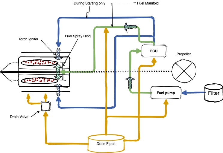
Fuel flow is measured between the FCU and the engine. Fuel is delivered to the inside of the Spray Ring, which is flange-mounted on the compressor rotor shaft. This ring has several holes, spraying the fuel outwards into the combustion chamber as a fine mist.
The cavity on the inside of the spray ring is sealed by labyrinth seals to prevent leakage. This arrangement gives a level of inherent protection against some fuel impurities or other events that could cause high-pressure fuel nozzles to clog.
During abnormal operations, the Isolation Valve can be opened allowing fuel to bypass the FCU and in effect “isolates” it. The Fuel Stop Cock/Emergency Power Lever is set to deliver idling fuel. Operating this lever will directly introduce fuel to the engine, bypassing any- and all safety and governing devices. In reality, valves inside the FCU supplies fuel directly to the Emergency Power Lever (EPL) metering valve, which controls fuel flow in direct relation to the position of the EPL. Care must be taken to open the EPL slowly while monitoring ITT and N1, not faster than six seconds.
Starting
Before starting, the following should be set (provided the Main Circuit Breakers, under the plastic cover, is properly set for flight):
- Sufficient electrical power. Either Internal Batteries and/or External Power must be on. The minimum Voltage for starting is 24V for starting with batteries, 20V for starting with External Power.
- Engine Start Switches ON.
- IELUs ON.
- Fuel Boost Pumps ON. It is acceptable, to conserve internal battery power, to switch only the booster pump of the engine being started to ON.
- No #1 26V AC Inverter ON. In the case of near-low battery state, this can be omitted, however, Oil and Fuel Pressure will not be indicated. The related Annunciators will still function.
- Airmanship: The Rotating Beacon and Fasten Seatbelt Signs should be ON, and the area around the aircraft should be clear.
Prior to start, the pilot should check that ONLY the OIL PRESSURE annunciator remains illuminated for the engine being started.
Starting the aircraft is a dual crew operation. The Pilot Flying should focus attention to the N1 and ITT rise-rates, while the Pilot not Flying should call the supporting aspects, as given below.
The starting cycle is automated and lasts ~20 seconds. The start cycle is as follows:
STARTER BUTTON – PRESS. PF calls “Starting”
- The Starter-Generator engages, rotating and accelerating the engine. Power is provided to the low voltage igniters, as well as the starting circuit of the FCU.
- The FO should monitor that Volts does not drop below 14V for more than 4 seconds.
- As the N1 increases, the FCU sends fuel to the Torch Igniters and Fuel Distributor.
- Ignition should occur within 10 seconds of Fuel Flow registering.
- As the ITT rises, the IELU will monitor the rate of ITT rise, and reduce the fuel flow as needed. This causes the characteristic “stepped” start of the engine, with ITT rising in stages, even falling as the IELU Intervents.
- The pilot should monitor the rate of N1 rise as well as ITT and be ready to promptly move the Fuel Stop Cock/Emergency Power Lever to Cut-Off in case of ITT exceeding maximum (700°C with external power, 730°C with batteries), or slightly advance the Throttle Control Lever if near the end of the start cycle the N1 remains sluggish to increase to 60%. In that case, the ITT should be carefully monitored.
- In case of an engine fire, or ITT exceeding maximum and start is to be terminated, the following is to be considered:
- Move Fuel Stop Cock / Emergency Power Lever to Cut-Off.
- This will cut off all fuel to the engine, but the engine will continue motoring. The two low voltage spark igniters will still spark during this period but the fuel provided is cut off.
- Allowing the engine to continue motoring will draw the flames out of the engine.
NOTE: After the start, the engine must be allowed to warm up minimum 2 minutes, or as required for the oil temperature to reach 30°C, before exceeding 70% N1 (aircraft can taxi).
Controls
The engine controls are:
- Controlling Levers:
- Throttle Control Levers.
- Fuel Cut-Off/Emergency Power Levers.
- Firewall Shut-off Cocks
- Propeller control levers
- Associated Friction Control Levers
- Overhead Switches:
- Engine Start (L/R)
- IELU (L/R)
- Auto Bank Control
- Auto Feather Control
- Isolation Valve (L/R)
- Centre Console Switches:
- Manual Feather (L/R)
- Water Injection Control
- Engine Motoring (L/R)
- Engine Start (L/R)
- Auto Bank Control
- Auto Feather Control
Indications
The ITT and N1 gauges show the working of the Gas Generator, or it can be viewed as how hard the “jet engine” part is working. The Power Turbine, tapping the gas-flow from the Gas Generator, converts the energy into shaft horsepower, which can be expressed by the formula
The [277.3] is a constant derived from a unit of measurement, in this specific case of using percentage for Torque, maximum Take-Off Power is expressed as:
The Torque and NP gauges thus show how the energy generated by the “jet engine” part is converted into thrust. It can be visualised that at a high NP, there is “more time” to generate thrust, thus at a lower NP the Torque has to increase to develop the same amount of thrust. It is important to note that NP per se does not affect shp, but a linear relationship exists between Torque and NP, if the Power Levers are not moved, Torque will increase with a decrease in Propeller RPM and vice versa.
However the maximum amount of torque is normally limited at 100%, therefore NP affects the maximum power that may be set moving the Power Levers, as follows:
- At pitch fully fine, 2080 NP: max shp is
- At Climb Power, 1900 NP: max shp is
- At Cruise Power, 1700 NP: max shp is
- Equally, Maximum Contingency Power is
Torque Gauges need 36V AC Power to operate. The ITT, N1 and NP gauges do not require electrical power as the systems are self-powering. The Fuel Flow Gauge needs 28V DC Power.
The “Triple Gauge” shows the health state of the engine, not its operation. Fuel pressure is shown on top, and should always be viewed with a steady fuel flow indication. High or low Oil temperature and pressure can be indicative of a potential problem. A sudden drop to zero of Oil Pressure, not accompanied by the Oil Pressure Annunciator, can be the fault of the instrument. Oil Temperature and Fuel Pressure needs 28V DC power, while Oil Pressure requires 36V AC Power.
An FCU Failure can reduce power on the affected engine to idle conditions, but should not cause engine flame-out. This can be recovered by switching the Isolation Valve ON and operating (carefully) the appropriate Emergency Power Lever. Indications typical of the FCU failure are (showing left engine affected):
- Torque: Significant Torque Reduction (without feathering the propeller, will be close to zero)
- ITT: Not significantly less, as opposed to a flame-out (below). Typical ITT is around 450°C.
- N1: In the idling range.
- NP: Will be lower than normal but still high until feathered manually or by the Auto-Feather system.
- Triple Gauge: Except for Fuel Pressure the indications of the Triple Gauge should be normal. Fuel Flow is in the idling range.
Conclusion: The give-away of this condition is N1 in the idling range, ITT around 450°C, and no engine response to Power Lever movement. Place the Power Lever in the idle position and use the Emergency Power Lever to recover the engine.
Another case is when the combustion process has disrupted to such an extent that a flame-out has occurred. Without combustion the engine will roll back to N1 settings commensurate with airflow through the engine, i.e. it is wind-milling. The indications are:
- Torque: zero.
- ITT: very low and falling as the engine cools down. In the case above just after the flame-out, the ITT is measuring residual engine heat which is dissipating with time. Sustained combustion is simply not possible at 200°C or below.
- N1: Very low but not zero. 5% N1 is a typical wind-milling N1 at 203kmh/110KIAS. It is important that some N1 is indicated, as a 0% N1 indication can indicate mechanical failure and/or seizure of the engine.
- NP: With the propeller feathered, a zero indication is typical. It should have been observed however that the propeller did not grind suddenly to a halt, but stopped smoothly as a result of feathering it, as a sudden stop can also indicate a mechanical failure in the reduction gearbox/propeller section.
- Triple Gauge: Zero oil pressure and fuel pressure.
- Fuel Flow: Zero.
Conclusion: The very low ITT and N1 indicate that the engine ceased combustion. Remaining N1 indicates wind-milling, which is important in assessing the chances of a successful restart. If N1 is zero, previously accompanied by a sudden, noisy stoppage, you have to rapidly accept the fact that for the remainder of the flight you are flying a single-engined aircraft.
NOTE: Even after oil pressure has dropped to zero, the propeller will not automatically feather on its own, if Auto-Feather was not operational. Manual Feather has to be used to feather the propeller.
Limitations
- Starting, internal batteries: 730°C Max ITT
- Starting, external power: 700°C Max ITT
- Maximum number on start attempts, including engine motoring, in one hour allowing at least 2-minute intervals, is 5.
- Minimum Voltage for engine start with external power: 20V
- Minimum Voltage for engine start with batteries only: 24V
- Minimum Voltage that Volts may drop, for 4 seconds maximum, during start: 14V
- Minimum Oil Temperature for start: -20°C
- Minimum Oil Temperature for applying power: 30°C (not above 70% N1).
- Maximum Oil Temperature: 85°C (With Maximum Contingency Power, 95°C)
- Minimum Oil Pressure: 1.2kp/cm2 (17.1 psi)
- Maximum Oil Pressure: 2.7kp/cm2 (38.4 psi). Note at starting below 0°C, a temporary Oil Pressure increase to 3.5kp/cm2 (49.8 psi) is allowed.
- Maximum Altitude with Auto-Feather ON: 10000’ AMSL.
- Maximum ITT increase with Heat ON, 30°C
- Reverse not allowed when:
- In-flight
- Using the Emergency Fuel System
| Power Rating | ITT °C | Torque% | N1% | Np | Oil | Time limit | Note | |
|---|---|---|---|---|---|---|---|---|
| Press | Temp °C | |||||||
| Maximum Contingency | No limit | 106.5 | No limit | 2080 | 1.8 - 2.7 Note 3 |
+20°C - +85°C Note 4 |
6 mins | 1 |
| Intermediate Contingency | 735° | 100 | 100 | 2080 | 1.8 - 2.7 Note 3 |
+20°C - +85°C Note 4 |
1 Hour | 2 |
| 750 | 1 Hour / TBO | 5 | ||||||
| Max Take-Off | 735° | 100 Note 6 |
100 | 2080 | 1.8 - 2.7 | +20°C - +85°C | 5 min | - |
| Take-Off with Water Injection | Same as above, but limited to 1 minute with water | 7 | ||||||
| Maximum Continuous | 690° | 100 | 97 | 1900 | 1.8 - 2.7 | +20°C - +85°C | No limit | - |
| 80% Max Continuous | 690° | 100 | 94 | 1700 | 1.8 - 2.7 | +20°C - +85°C | No limit | - |
| Idle | 550° | - | 60 - 63 | - | Min 1.2 | -20°C - +85°C | No limit | - |
| Starting Batteries | 735° | - | Min 18 | - | Max 3.5 if below 0°C | Min -20°C | 45 secs | - |
| Starting External Power | 700° | - | Min 18 | - | Max 3.5 if below 0°C | Min -20°C | 45 secs | - |
| Transient during Engine Acceleration | 735° | 106 | 101 | 2140 Note 8 |
1.8 - 2.7 | +20°C - +85°C | 5 sec below 13000', 6 sec aboce 13000' | 9 |
| Max Reverse | 710° | - | 97 | 1900 | 1.8 - 2.7 | +20°C - +85°C | 1 min | 10 |
| Using Emergency Power Levers | 710° | 100 | 99 | 2080 | 1.8 - 2.7 | +20°C - +85°C | 1 hour | 11 |
NOTE:
- After Maximum Contingency, Intermediate Contingency can be used for 30 minutes.
- Use for 1 hour only in case of engine failure.
- If the oil temperature is +20°C to 55°C, an increase of 0.3kp/cm2 is allowed.
- An increase of oil temperature to +95°C is allowed when using Contingency Power.
- Only to be used during engine failure operations at OAT of +30°C, or as required. The engine needs to be oveR/Hauled.
- During Take-Off, a temporary Torque of 106% is allowed, provided other parameters are not exceeded.
- Water Injection is permitted:
- Above +23°C,
- Above +15°C between 2600’ AMSL to 4200’ AMSL.
- Above +10°C above 4200’ AMSL.
- Throttle Control Lever should not be moved faster than 1 second. A maximum of three “over-swings” are allowed.
- Maximum transient is 2200RPM.
- Reverse power figures are for Sea Level ISA conditions. N1 may increase and torque decrease for conditions of higher density altitude.
- Do not move the Emergency Power Lever, increasing power, in less than 6 seconds.
Interaction / Dependencies on Other Systems
ABC Tabs
At speeds below 205kmh/111KIAS, a large rudder deflection required to offset the drag caused by the ABC tab. Tests show minimal loss of performance, however, controllability is seriously compromised at airspeeds close to VR. If Maximum Contingency Power is used just after Rotate, ABC Tab operation may be required to maintain directional control, depending on circumstance, aircraft rigging, etc. In the case of Hydraulic failure, this system will not be operational.
Auto-Feather
This system should be tested prior to the first flight of the day. If this system is not operational, the briefing should include the identification, verification and securing of an engine in case of failure.
Electrical Power Supply
Certain engine instruments as indicated above, are dependent on the electrical power supply, as is ABC Tabs and Auto-Feather systems.
Radio Altimeter
This instrument supplies height information to the IELU system. Water. Distilled water is used for the Water Injection System.
Recent posts
-
Behind the Scenes - Adventures in 3D Scanning of the L-410
Nov 19, 2023
Our new journey took an unexpected turn as we dove deep into reworking our 3D model. The challenges were real, but so was our determination to achieve a level of quality that would redefine the standards in our upcoming 2.0 version.
-
The Devil is in the details
Mar 7, 2022
In the past months, even I wasn’t sharing much - loads of things have happened.
-
Why the Turbolet?
Apr 11, 2021
While I'm working on one of the most boring parts of the plane - the electric system - I'm trying to break the long silence
-
Cabin lights and lamps
Jan 16, 2021
I was finishing work on Friday, back of my mind was already working on the Turbolet’s CWS lamps. The logic was already there but couldn’t test it properly without the actual lamps in the cockpit.
-
Visual update 2 - cockpit and cabin
Dec 14, 2020
We all know how crazy this year was. But I'd like to talk about the progress we made with the Turbolet :)
-
Engines, and it's limitations
Nov 15, 2020
The Let L-410 is powered by two Walter/General Electric Turbo-Propeller engines. The engines have several protections and redundancy mechanisms and are equipped with a water injection system...
-
Systems - Central Warning Display (CWD)
Nov 1, 2020
In this post we go through the Central Warning Display annunciators...
-
Systems - How deicing works
Jul 13, 2020
The Turbolet has the following systems on the aircraft front sections as the protection against the ice formation...
-
Textures, animations and love!
May 30, 2020
After a long hesitation, I teamed up with a 3D/texture artist, Andrei Nastasa. He re-did all the external textures and made it look exceptionally realistic!
Comments