#devblog
Sharing, ranting, showing-off :)
Systems - How deicing works
Jul 13, 2020
Deicing systems on the Turbolet
The Turbolet has the following systems on the aircraft front sections as the protection against the ice formation:
- the pneumatic deicing system for deicing the leading edges of wings and tail unit
- the system of hot-air heating of leading edges of the engine air intakes
- the system of the electric heating of the Pitot tubes, static and ram pressure heads
- the system of heated front windshield including the installation of the wiper unit for removal of the hoarfrost, snow, ice and dust from the pilotcs cabin windshields
- the system of the electric heating of the propeller blades
Windshield heat
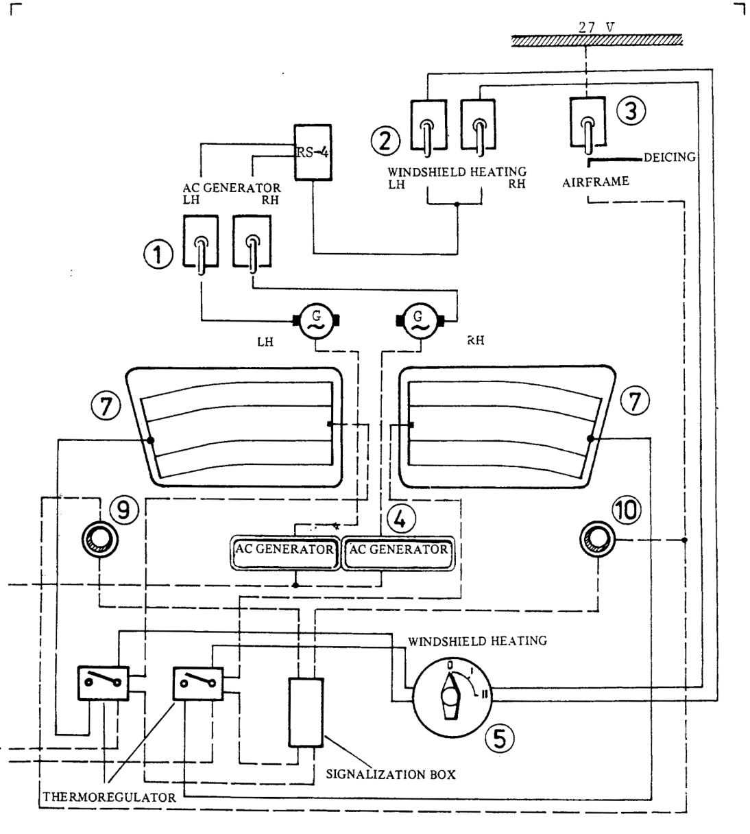
The electric heating of the heated windshields system is a two-stage one. In the 1st stage, the entire areas of both windshields are heated up to 30% of the power when both AC generators are operating. In the IInd stage, the entire
areas of both windshields are heated up to 100% of the power when AC generators are operating.
In case of failure of one AC generator, the entire regime of the windshield heating is transfered automatically onto the other AC generator.
The system is actuated by switching on the switches BATTERY
I, II, WINDSHIELD HEATING LH, RH the circuit breakers AC GENERATOR LH, RH, CENTRAL WARNING DISPLAY and by switching over the selector WINDSHIELD HEATING to the Ist heating stage.
NOTE: Switching over of the selector WINDSHIELD HEATING to the
IInd stage is only possible after 5 to 7 minutes of the windshield heating at the 1st stage.
The operation of individual heating sections is controlled automatically by means of the thermoregulator mounted in the windshield and set up to the temperature of 30C.
If exceeding the set up temperature, the heating is switched of automatically. The closing of the windshield heating system is signalized by the green signal lights WINDSHIELD HEATING, mounted on the glareshield of the instrument panel. The function of the thermoregulator is checked
by the switches TEST OF WINDSHIELD HEATING.
Propeller deicing
Propellers are electrically deiced by means of the heating elements glued on the leading edges of the propeller blades.
The deicing-system of the propellers consists of two-sections: parts rotating together with the propeller /transfer rings and deicing elements of the propeller blades/ and parts not rotating, installed inside the airframe /timers, collectors, contactors, switches, push-buttons, fuses and signal bulbs/.
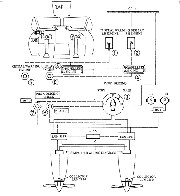
The deicing is realized within the cycle, the interval of
which has been set on the selector - PROPELLER DEICING - I, II, STBY-MAIN on the instrumental panel.
The selector position I /closer to the neutral/ corresponds to the interval of 40 sec., the position II /more distant/ corresponds to the interval of 80 sec.
Under normal conditions the MAIN circuit of the cycler is selected. The correct function of the propellers deicing is indicated so, that both signal cells PROPELLER DEICING on the signalling block LEFT ENGINE, RIGHT ENGINE are extinguished.
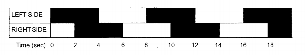
The interval of the propellers deicing cycle can be shortened t o 4 sec. by switching over the selector PROPELLER DEICING to the position MAIN, and by pressing the push-button TIMER on the left control panel.
When the cycle controls are working correctly, the PROPELLER DEICING cells on the CWD must come
on for 4 seconds every eighth second, with a two-second overlap between the LH and RH sides, as
shown below; another timing indicates a system defect.
Pitot and static probes
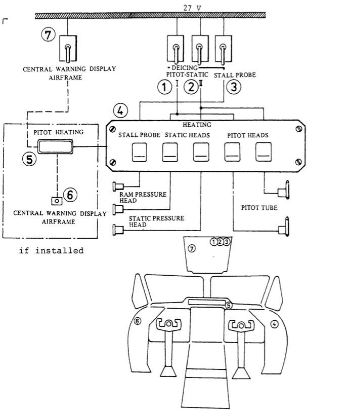
Pitot tubes, static pressure heads and ran pressure head have their own inner heating by means of the DC current. Heating of the Pitot tubes is accomplished by means of heating elements of 140W power, installed directly inside the Pitot tubes.
After switching on all push-button switches HEATING, on right control panel, the signal light PITOT HEATING will go off. In case of circuit failure the signal light PITOT HEATING will light up.
The signal light PITOT HEATING is also ON, when not all the push-button switches are on.
CAUTION: ON THE GROUND, WHEN THE AIRCRAFT IS AT THE STAND-STILL, THE HEATING CAN ONLY BE SWITCHED ON FOR A SHORT TIME JUST FOR CHECKING ITS FUNCTION.
The operation of the Pitot-static system heads and the stall probe heating when the airplane is on the ground is limited as follows:
  - at ambient temperatures above O°C (32OF) ................. 1 minute maximum
  - at ambient temperatures below O°C (32OF) ................. 3 minutes maximum
Airframe deicing
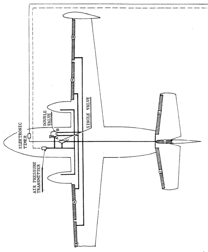
The pneumatic deicing system serves for the ice removal from the leading sections of wings and tail unit. The function of the deicer is based on the mechanical action of the flexible rubber jacket, which is fixed to the leading edge of wings and tail unit. In this deicer, there is a series of small cells, and their quick filling with air causes the fracturing of the ice accretion layer, which in this way is released from the surface and then removed by means of the air stream.
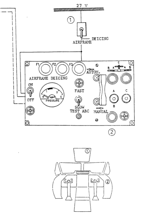
The actuation of the pneumatic deicing system is carried out by turning on the circuit breaker DEICING-AIRFRAME mounted on the overhead panel. The main switch is turned to the position ON hence putting the deicing system into operation. On the control box of the airframe deicing 3 bulbs light up. The selector of the operation is in the position AUTOM. The cycling is accomplished by help of the electronic timer, this switching on separate solenoid air valves and in this way the air stream is fed to the separate sections of the rubber deicers /sections A, B, C/ and the cells in the deicers are inflated.
Upon completing the deicing, the electronic timer sets individual solenoid air valves so, that the Venturi tube starts operating, this being a part of the solenoid air valves. The negative pressure appears in the system and the cells in the deicers get flat. This is repeated continuously, till
the main switch on the control box of the airframe deicing
does not turn off. The filling of deicers with the pressure
air is checked on the pressure gauge inside the control box. Switching over individual sections is indicated by the
lighting up of the control lights on the control box /always for the relevant section A or B or C/. Cycling can either be speeded up or slowed down by the speed selector FAST-SLOW
which is also mounted on the control box.
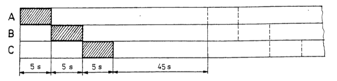
The diagram of the work cycle for the automatic control - the speed selector is in the position FAST
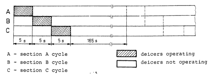
the speed selector is in the position SLOW
In case, we don’t want to use the automatic cycling, the operation selector is switched to the position MANUAL and the cycling is accomplished by switching over individual sections to the position A, B or C. Even in the case that the system of the pneumatic deicing is not put into aperation, it is necessary to turn on the circuit breaker DEICING-AIRFRAME, mounted on the overhead panel immediately upon starting the engines.
Recent posts
-
Behind the Scenes - Adventures in 3D Scanning of the L-410
Nov 19, 2023
Our new journey took an unexpected turn as we dove deep into reworking our 3D model. The challenges were real, but so was our determination to achieve a level of quality that would redefine the standards in our upcoming 2.0 version.
-
The Devil is in the details
Mar 7, 2022
In the past months, even I wasn’t sharing much - loads of things have happened.
-
Why the Turbolet?
Apr 11, 2021
While I'm working on one of the most boring parts of the plane - the electric system - I'm trying to break the long silence
-
Cabin lights and lamps
Jan 16, 2021
I was finishing work on Friday, back of my mind was already working on the Turbolet’s CWS lamps. The logic was already there but couldn’t test it properly without the actual lamps in the cockpit.
-
Visual update 2 - cockpit and cabin
Dec 14, 2020
We all know how crazy this year was. But I'd like to talk about the progress we made with the Turbolet :)
-
Engines, and it's limitations
Nov 15, 2020
The Let L-410 is powered by two Walter/General Electric Turbo-Propeller engines. The engines have several protections and redundancy mechanisms and are equipped with a water injection system...
-
Systems - Central Warning Display (CWD)
Nov 1, 2020
In this post we go through the Central Warning Display annunciators...
-
Systems - How deicing works
Jul 13, 2020
The Turbolet has the following systems on the aircraft front sections as the protection against the ice formation...
-
Textures, animations and love!
May 30, 2020
After a long hesitation, I teamed up with a 3D/texture artist, Andrei Nastasa. He re-did all the external textures and made it look exceptionally realistic!
Comments