#devblog
Sharing, ranting, showing-off :)
Systems - Central Warning Display (CWD)
Nov 1, 2020
The idea behind the Turbolet’s annunciator panels is that in normal flight conditions all annunciators should be OFF - so when you see something, you know for sure something is up! The colour or each light signal has it’s own importance level:
- GREEN means active states of supplementary systems, eg.: TIP FEED, AUTO FEATHER, etc.
- AMBER means abnormal state of a system that need crew attention, or the plane is not takeoff-ready, eg.: MANUAL STEER
- RED means immediate action required from the flight crew, or the plane is prohibited from flying, eg.: DOOR

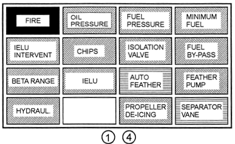
Left and Right Engine annunciator panels (1,4)

| Light Signal | Indicated State |
|---|---|
| FIRE | Illuminates when any of the three sensor circuits detects an abnormal high temperature in the respective engine nacelle. Accompanied by fire bell alarm. |
| OIL PRESSURE | Oil pressure is less than 1.2kp/cm2 (17.1 psi) |
| FUEL PRESSURE | Fuel pressure is less than 0.3kp/cm2 (4.27 psi) |
| MINIMUM FUEL | Fuel in relevant main tank is less than 108kg ±5kg (238 ± 11lb) |
| IELU INTERVENT | The engine fuel flow has been reduced in response to the IELU. |
| CHIPS | Metal chips have been detected on the magnetic chip detector(s). |
| ISOLATION VALVE | Automatic or manual feathering of failed engine (torque dropped below 18%, refer technical description), or: Isolation Valve has been manually switched ON. |
| FUEL BYPASS | The fuel filter has been blocked and is currently in by-pass mode. |
| BETA RANGE | The propeller pitch is below the hydraulic low pitch stop (flight idle minimum) |
| IELU | The Integrated Electronic Limiter Unit is switched OFF manually, or automatically following a failure of the other engine. |
| AUTO FEATHER | Auto-Feather system is armed, with Power Control Lever set to more than 88% or NG more than 92%. |
| FEATHER PUMP | Propeller Feather Pump is running. |
| HYDRAUL. | The temperature of the hydraulic fluid is higher than 85°C. |
| PROPELLER DE-ICING | Failure detected of the Propeller De-Ice system, including contacts. |
| SEPARATOR VANE | While the Separator Vane is opening or closing, the annunciator will flash green, upon reaching open will illuminate steady green, and OFF when closed. |
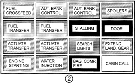
Airframe annunciator panel (2)

| Light Signal | Indicated State |
|---|---|
| FUEL CROSSFEED | Fuel crossfeed valve is open. |
| AUT BANK CONTROL | Automatic Bank Control Circuit is armed. |
| AUT BANK CONTROL | Automatic extension of an Automatic Bank Control Tab |
| SPOILERS | Spoilers are deployed. |
| FUEL TRANSFER | Fuel transfer from the Left Tip Tank to the Left Main Tank is active. |
| FUEL TRANSFER | Fuel transfer from the Right Tip Tank to the Right Main Tank is active. |
| STALLING | Airspeed ±14 km/h (±8 KIAS) above stalling. |
| DOOR | Main entry, one of the three emergency exits, or one of the nose baggage doors are not locked properly. |
| ACTUATE TRANSFER | Fuel in Left Main Tank is down to 220kg (with fuel in Tip Tank), but fuel transfer has not been selected, or: fuel transfer from Tip Tank failed. |
| ACTUATE TRANSFER | Fuel in Right Main Tank is down to 220kg (with fuel in Tip Tank), but fuel transfer has not been selected, or: fuel transfer from Tip Tank failed. |
| SEARCH LIGHTS | Search Lights switched ON. |
| EXTEND LAND. GEAR | Flaps extended (18° or 42°) with Landing Gear retracted, both engines IDLE, Landing Gear retracted and speed below 205 km/h (111 KIAS). Continuous horn that cannot be silenced. |
| ENGINE STARTING | Starter-Generator in START mode, should remain ON for 20 secs, if more than 20 secs it indicates a fault. |
| WATER INJECTION | Operating pressure in the Water Injection System. |
| BAG COMP. FIRE | Smoke detected in the Front Baggage Compartment. |
| CABIN CALL | Someone in the back wants your attention :) |
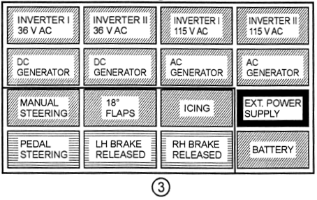
Electro annunciator panel (3)

| Light Signal | Indicated State |
|---|---|
| INVERTER I 36V AC | Loss of voltage from the #1 36V AC Inverter. |
| INVERTER II 36V AC | Loss of voltage from the #2 36V AC Inverter. |
| INVERTER I 115V AC | Loss of voltage from #1 115V AC Inverter. |
| INVERTER II 115V AC | Loss of voltage from #2 115V AC Inverter. |
| DC GENERATOR | Loss of voltage from the L/H DC Generator |
| DC GENERATOR | Loss of voltage from the R/H DC Generator |
| AC GENERATOR | Loss of voltage from the L/H AC Generator. |
| AC GENERATOR | Loss of voltage from the R/H AC Generator. |
| MANUAL STEERING | Nose Wheel Steering in MANUAL Mode. |
| 18° FLAPS | Wing Flaps not 18° on ground (either 0° or 42°). |
| ICING | Rotary Ice Detector detected ice. |
| EXT POWER SUPPLY | External electrical power is connected to the aircraft’s main DC busses. |
| PEDAL STEERING | Nose Wheel Steering in PEDAL Mode. |
| L/H BRAKE RELEASED | Antiskid System released L/H Brake Pressure. |
| R/H BRAKE RELEASED | Antiskid System released R/H Brake Pressure. |
| BATTERY | One or both of the Batteries are disconnected. |
To sum up: when you see something on the CWD - it needs your attention and you have to act. If it’s an in-flight red warning (eg.: STALL, DOORS) it means a serious issue, so you have to act fast to prevent a catastrophic event. Train your eye where to look for each level of importance and make sure you understand them in the shortest time, so you can act fast!
In the next chapter we go through the engine, and it’s limitations.
Recent posts
-
Behind the Scenes - Adventures in 3D Scanning of the L-410
Nov 19, 2023
Our new journey took an unexpected turn as we dove deep into reworking our 3D model. The challenges were real, but so was our determination to achieve a level of quality that would redefine the standards in our upcoming 2.0 version.
-
The Devil is in the details
Mar 7, 2022
In the past months, even I wasn’t sharing much - loads of things have happened.
-
Why the Turbolet?
Apr 11, 2021
While I'm working on one of the most boring parts of the plane - the electric system - I'm trying to break the long silence
-
Cabin lights and lamps
Jan 16, 2021
I was finishing work on Friday, back of my mind was already working on the Turbolet’s CWS lamps. The logic was already there but couldn’t test it properly without the actual lamps in the cockpit.
-
Visual update 2 - cockpit and cabin
Dec 14, 2020
We all know how crazy this year was. But I'd like to talk about the progress we made with the Turbolet :)
-
Engines, and it's limitations
Nov 15, 2020
The Let L-410 is powered by two Walter/General Electric Turbo-Propeller engines. The engines have several protections and redundancy mechanisms and are equipped with a water injection system...
-
Systems - Central Warning Display (CWD)
Nov 1, 2020
In this post we go through the Central Warning Display annunciators...
-
Systems - How deicing works
Jul 13, 2020
The Turbolet has the following systems on the aircraft front sections as the protection against the ice formation...
-
Textures, animations and love!
May 30, 2020
After a long hesitation, I teamed up with a 3D/texture artist, Andrei Nastasa. He re-did all the external textures and made it look exceptionally realistic!
Comments